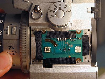
On its back, we can see the command dials:
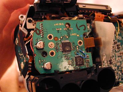
After removing the visible screws, we can look unter the PCB (printed circuit board)
and have a first glimps of true high-tech:

Anyway, that won't get us far. We need to detach the rear panel.
To do this, remove all the silver screws on the bottom of the camera
that belong to the rear panel.
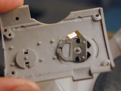
Also remove two screws just above the four AA battery compartments.
I recommend you also remove three screws in the CompactFlash compartment.
Bring the EVF (electronic viewfinder) into its most vertical position.
Unscrew the two screw that are now reavealed.
Make sure the EVF is vertical when you encounter any resistance.
Carefully wiggle&jiggle the rear panel away from the rest of the camera.
Be careful not to detach it to far, it is connected by wires to the main PCB:
To remove the rear panel completely, use a fairly large flat
screwdriver to loosen the connector:
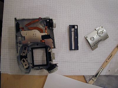
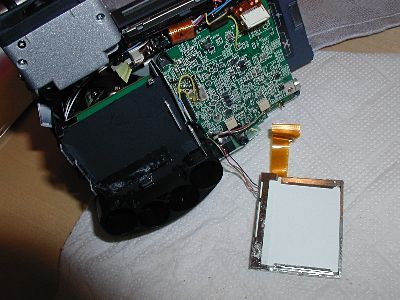
You now should have removed the following main parts:
Now, it really gets difficult.
We have to unscrew screws that are hidden deep inside of our dimage!
You probably noticed the LCD sitting ontop of the lens assembly.
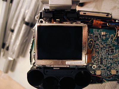
The LCD sits on a silver carrier.
Firstly, loosen the greyish bracket around
the white connector on the main PCB (with your fingernails for example).
This will make the thin orange cable so loose that
you can pull it out gently with your fingers.
I haven't found a way to loose the power-connector yet :(

Now remove the LCD carefully from the carrier.
It is not _that_ easy, because it is actually glued onto the carrier
in the lower region by some sort of double sided tape or the like.
I suggest you use some sort of plastic plate or similar
(or a large screwdriver when you are really careful)
and loosen the LCD by wiggle&jiggle ;)
You then should have something like this:
Ok, still with me? Now, next are the three screws holding the carrier.
The first one is simple. On the upper left corner of the carrier.
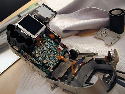
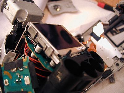
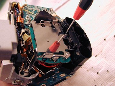
Now, the second one is more difficult.
To reach this screw, you have to unscrew the single
screw that holds the PCB-support you can see in front of the LCD here:
Be careful not to bend the cables too much!
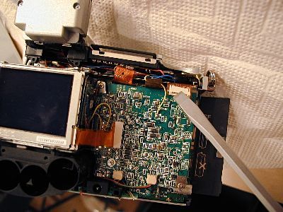
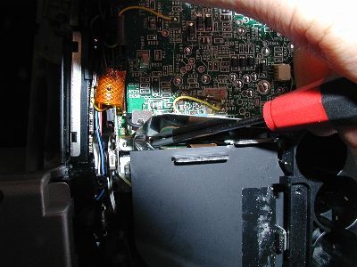
Now, don't make the same mistake I did!
Do NOT unscrew this screw:

It is not necessary to remove this screw to remove the LCD carrier!
To reach the last screw holding the LCD carrier,
I removed the black plastic cover.
I think that is not necessary. You will notice that the black plastic foil is
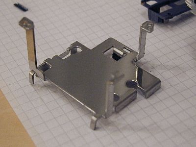
partly reaching farther than the carrier itself.
In this picture you can see a small metall "lip" on the lower edge
(to the right in the picture) of the carrier.
Just right to this "lip", peel up the plastic foil and put a screwdriver down,
until you engage a screw.
Now, that was too risky for me. That's why I removed not only the black foil,
but I also cut away some plastic of the battery compartment.
I could therefore put the screwdriver in absolutely perpendicularly.
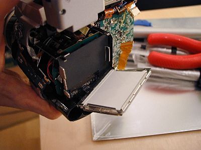
After removing this third screw (don't let it fall into the camera),
you can carefully take out the carrier:
(please note: Once out, I trimmed the foot of the carrier that is closest to the battery compartement - this makes inserting and taking it out much easier. But it also reducers stiffness of the assembly.
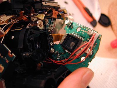
Underneath you'll see the PCB that holds the CCD chip:
Now, which screws do you remove?
I'll tell you: The three black ones. Do NOT remove the single silver screw!
Now, you can lift up the PCB and take a look into the Minolta's awesome GT lens:
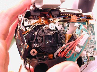
or watch 5MP on a single chip:
(here with the IR cut filter already removed)
You can carefully take out the IR cut filter from its rubber sealing
with your fingers or plastic tweezers.
Here my adventure of disassembling the Dimage D7 ends.
To read the steps needed to complete the conversion to a D7IR, continue here.
If you take the disassembly any further, I'd like to hear from it.